Ready to hit the road with your trailer in tow? Before you embark on that epic adventure, ensuring your trailer lights are correctly connected is paramount for both safety and legality. This comprehensive guide dives deep into the world of 5-pin trailer wiring diagrams, equipping you with the knowledge to conquer trailer lighting like a pro.
A 5-pin trailer wiring diagram is your roadmap to a successful trailer lighting setup. It’s the key to understanding which wire from your vehicle connects to which function on your trailer, enabling everything from brake lights and turn signals to running lights. Without a proper understanding of this electrical blueprint, you risk faulty connections, short circuits, and potential hazards on the road.
While the exact origins of the 5-pin connector are difficult to pinpoint, its standardization represents a crucial step in simplifying trailer connectivity. Before standardized connectors, wiring trailers was often a complex and customized process, leading to compatibility issues and frustration. The 5-pin connector emerged as a common solution for lighter trailers, offering a relatively simple and consistent way to manage the essential lighting functions.
The importance of a correct 5-pin trailer wiring schematic cannot be overstated. A correctly wired trailer ensures that your intentions on the road are clearly communicated to other drivers, mitigating the risk of accidents. Properly functioning brake lights and turn signals are critical for signaling stops and lane changes, while running lights make your trailer visible at night and in low-visibility conditions. Incorrect wiring can lead to malfunctioning lights, potentially causing confusion and dangerous situations for yourself and other drivers.
One of the most common issues encountered with 5-pin trailer wiring diagrams is mismatched wiring. This can occur due to variations in wiring color codes between vehicle manufacturers or using an incorrect diagram. Another common problem is corrosion in the connector itself, leading to poor electrical contact and intermittent lighting issues. Understanding the functions of each pin and employing proper wiring techniques can prevent these problems and ensure reliable trailer lighting.
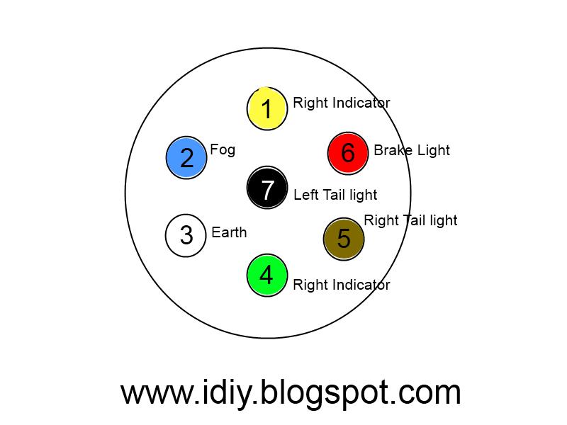
Each pin on the 5-pin connector has a specific function: Pin 1: Ground, Pin 2: Brake lights, Pin 3: Running lights, Pin 4: Right turn & brake light, Pin 5: Left turn & brake light. A simple example: connecting the ground wire from your vehicle to the ground pin on the trailer connector ensures a complete electrical circuit.
Benefits of Understanding Your 5-Pin Trailer Wiring Diagram:
1. Enhanced Safety: Properly functioning trailer lights are crucial for safe towing, preventing accidents and ensuring visibility on the road.
2. Legal Compliance: Adhering to legal lighting requirements avoids potential fines and keeps you on the right side of the law.
3. Simplified Troubleshooting: A clear understanding of the wiring diagram makes diagnosing and fixing lighting issues easier and faster.
Step-by-Step Guide to Wiring a 5-Pin Connector:
1. Gather your materials: 5-pin connector, wiring, wire strippers, crimping tool, heat shrink tubing (recommended).
2. Identify the wires on your vehicle and trailer using the appropriate wiring diagram.
3. Strip the insulation from the ends of the wires.
4. Crimp the corresponding wires from the vehicle and trailer to the appropriate pins on the connector.
5. Apply heat shrink tubing to the connections for added insulation and protection (recommended).
6. Test the connections using a test light or multimeter.
Advantages and Disadvantages of 5-Pin Trailer Wiring
| Advantages | Disadvantages |
|---|---|
| Simple and easy to install | Limited functionality (no reverse lights or auxiliary power) |
| Standardized connection | Susceptible to corrosion if not properly maintained |
| Cost-effective solution for basic lighting | Not suitable for trailers with more complex lighting needs |
FAQ:
1. What if my trailer uses a different connector? Adapters are available to connect different connector types.
2. Can I wire a 5-pin connector myself? Yes, with basic tools and the correct diagram.
3. What if my lights aren't working? Check the connections, fuses, and bulbs.
4. Where can I find a 5-pin trailer wiring diagram for my vehicle? Check your vehicle's owner's manual or reputable online resources.
5. What gauge wire should I use? Consult your vehicle and trailer specifications.
6. What are the color codes for trailer wiring? Color codes can vary, always consult the specific diagram.
7. How do I test my trailer lights? Use a test light or multimeter to check the connections.
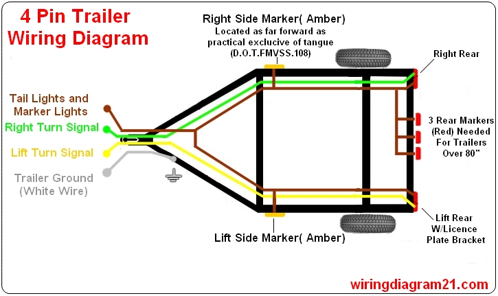
8. What is the difference between a 4-pin and 5-pin connector? The 5-pin includes a separate wire for left turn/brake, offering independent signaling.
Tips and Tricks:
Use dielectric grease on connections to prevent corrosion. Securely mount the connector to prevent damage. Always double-check your connections before hitting the road.
In conclusion, understanding and correctly implementing a 5-pin trailer wiring diagram is crucial for safe and legal towing. From enhancing road safety to simplifying troubleshooting, the benefits are clear. By following the steps outlined in this guide, you can confidently connect your trailer lights, ensuring a smooth and worry-free towing experience. Don't hit the road without being sure – double-check your connections and enjoy the journey knowing your trailer lighting is set up for success. Empower yourself with the knowledge and confidence to tackle any trailer lighting challenge, and remember that a well-maintained and correctly wired trailer contributes to safer roads for everyone. By taking the time to learn the basics of 5-pin trailer wiring diagrams, you are investing in both your safety and the longevity of your towing equipment. Don't underestimate the power of a correctly wired trailer - it's a simple step that can make a world of difference.
9 Way Trailer Connector Wiring Diagram - Trees By Bike
Trailer Plug And Wire - Trees By Bike
Wire Diagram For 7 Pin Trailer Plug - Trees By Bike
Wiring Car Trailer Plug - Trees By Bike
Pollak 6 Way Trailer Plug Diagram - Trees By Bike
Wiring A 7 Pin Trailer Plug Australia - Trees By Bike
Wire Diagram For 7 Pin Connector - Trees By Bike
7 Pin Flat Trailer Plug Wiring Diagram Nz - Trees By Bike
12 Pin Trailer Plug Wiring Diagram - Trees By Bike
Standard Trailer Plug Wiring Diagram at Demetrius Whitt blog - Trees By Bike
5 Pin Trailer Connector Wiring Diagram 6 Wire To 4 Wire Trailer Wiring - Trees By Bike
Wiring Diagram For 7 Pin Trailer Plug - Trees By Bike
Rv Wiring Color Code - Trees By Bike
Tractor Trailer Electrical Wiring Diagrams - Trees By Bike
Seven Pin Connector Wiring Diagram - Trees By Bike


