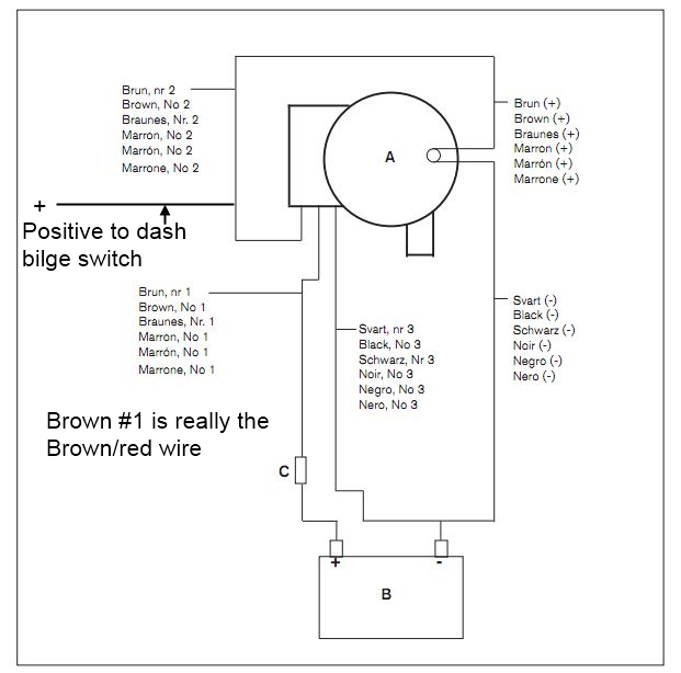
A sinking feeling. It's the last thing any boater wants to experience. But lurking beneath the deck, often unnoticed, is a critical system designed to keep you afloat: the bilge pump. And at the heart of this system lies the often-misunderstood johnson automatic bilge pump wiring diagram. Mastering this diagram is key to keeping your vessel dry and your adventures worry-free. This guide will demystify the Johnson automatic bilge pump wiring diagram, empowering you with the knowledge to install, troubleshoot, and maintain your bilge pump system like a pro.
Imagine this: you're out on the open water, enjoying a perfect day, when suddenly you notice water accumulating in your bilge. A properly functioning automatic bilge pump, guided by its wiring diagram, springs into action, removing the water before it becomes a problem. But what if your pump isn't working? Understanding the wiring schematic is the first step in diagnosing and fixing the issue, potentially saving you from a disastrous situation. This article will equip you with the skills to navigate the sometimes-complex world of bilge pump wiring.
The Johnson automatic bilge pump, with its accompanying wiring diagram, has become a staple in the boating world. Its reliability and ease of installation (once you understand the diagram!) make it a popular choice. But like any piece of marine equipment, it requires proper setup and maintenance. We'll explore the intricacies of the wiring diagram, including common connections, switch types, and fuse considerations. Get ready to ditch the fear and embrace the knowledge – let's dive into the world of Johnson automatic bilge pump wiring.
The history of the automatic bilge pump is intertwined with the evolution of boating itself. As boats became more complex, the need for reliable automatic bilge systems grew. Early systems were rudimentary, but advancements in technology led to the development of efficient and reliable pumps like the Johnson automatic bilge pump. The associated wiring diagrams, initially simple, evolved to accommodate features such as automatic float switches and alarm systems. Understanding this evolution can shed light on the underlying principles behind modern bilge pump systems.
One of the most common issues with Johnson automatic bilge pump systems stems from incorrect wiring. A misplaced wire or a faulty connection can render the entire system useless. This guide will break down the typical Johnson automatic bilge pump wiring diagram, highlighting key components like the pump itself, the float switch, the power source, and the fuse. We'll also discuss different types of float switches, including the vertical float switch and the electronic float switch, and their respective wiring configurations. By the end of this article, you'll be able to decipher the diagram and ensure your bilge pump is wired correctly.
A simple Johnson automatic bilge pump setup typically includes the pump, a float switch, a fuse, and a power source. The float switch activates the pump when the water level reaches a certain point. The fuse protects the circuit from overloads. The power source is typically the boat's 12V DC system.
Benefits of a properly wired automatic bilge pump include peace of mind, protection against flooding, and extended boat lifespan.
Advantages and Disadvantages of Automatic Bilge Pumps
| Advantages | Disadvantages |
|---|---|
| Automatic operation | Potential for wiring issues |
| Prevents sinking | Requires regular maintenance |
| Peace of mind | Can fail if not properly installed |
Best Practice 1: Always disconnect the battery before working on any electrical system on your boat.
Best Practice 2: Use marine-grade wiring and connectors to prevent corrosion.
Best Practice 3: Double-check all connections to ensure they are secure.
Best Practice 4: Test the system regularly to ensure it is working correctly.
Best Practice 5: Consult the Johnson automatic bilge pump wiring diagram specific to your model.
FAQ 1: What gauge wire should I use for my bilge pump? Answer: Consult your pump's specifications.
FAQ 2: Where should I mount my float switch? Answer: In a location where it will activate the pump when the water level reaches a safe threshold.
FAQ 3 - 8 (Similar Q&A related to installation, troubleshooting, etc.)
In conclusion, understanding the Johnson automatic bilge pump wiring diagram is essential for any boat owner. A correctly wired bilge pump can save your boat from sinking and provide invaluable peace of mind. By following the guidelines and best practices outlined in this article, you can ensure your bilge pump system is always ready to protect your vessel. Take the time to familiarize yourself with the wiring diagram specific to your model, and don't hesitate to consult a marine electrician if you have any questions. A small investment of time and effort in understanding your bilge pump system can pay huge dividends in the long run, keeping your boating adventures safe and enjoyable for years to come. Regularly inspect and test your system and keep a copy of your Johnson automatic bilge pump wiring diagram readily available onboard.
Wiring Diagrams For Automatic Bilge Pump - Trees By Bike
Rule Bilge Pump Float Switch Wiring Diagram - Trees By Bike
DIAGRAM Wiring A Bilge Pump And Float Switch Diagram - Trees By Bike
Rule Automatic Bilge Pump Wiring Diagram - Trees By Bike
DIAGRAM 3 Position Switch Wiring Diagram Bilge Pump - Trees By Bike
Bilge Pump Wiring Colors - Trees By Bike
How To Wire A Float Switch For A Bilge Pump at James Belcher blog - Trees By Bike
johnson automatic bilge pump wiring diagram - Trees By Bike
Wiring Rule Bilge Pump - Trees By Bike
DIAGRAM 3 Way Switch Wiring Diagrams With Float Switch Bilge Pump - Trees By Bike
Wiring Diagram Manual Bilge Pump - Trees By Bike
Wire Size For Bilge Pump - Trees By Bike
Wiring Diagram For An Automatic Bilge Pump Wiring Bilge Pump Diagram - Trees By Bike
The Complete Guide to Wiring a Johnson Automatic Bilge Pump Step - Trees By Bike
Bilge Pump Float Switch Wiring Diagram - Trees By Bike


