Ever wondered how to control your vehicle's accessories with the flick of a switch? Carling switches, renowned for their durability and versatility, are a common sight in automobiles, boats, and other vehicles. Understanding a Carling switch wiring schematic is essential for anyone working with these switches, whether you're installing a new accessory, troubleshooting a faulty circuit, or simply upgrading your existing setup. This comprehensive guide will delve into the intricacies of Carling switch wiring, providing you with the knowledge you need to confidently tackle any project.
Carling switch circuits aren't just about connecting wires; they are the backbone of your vehicle's electrical system. From powering your off-road lights to controlling your bilge pump, the proper configuration of these switches ensures reliable operation and prevents electrical hazards. A poorly understood Carling switch wiring setup can lead to malfunctions, blown fuses, or even damage to your vehicle's electrical components. Therefore, taking the time to learn the fundamentals is crucial.
The Carling switch, with its robust construction and varied configurations, has become a staple in the automotive and marine industries. Its history is rooted in providing reliable switching solutions for demanding environments. Early versions of these switches were crucial in providing control for essential functions, paving the way for the modern, feature-rich switches we see today. Their importance lies in their ability to handle high currents and withstand harsh conditions, making them ideal for controlling various electrical loads.
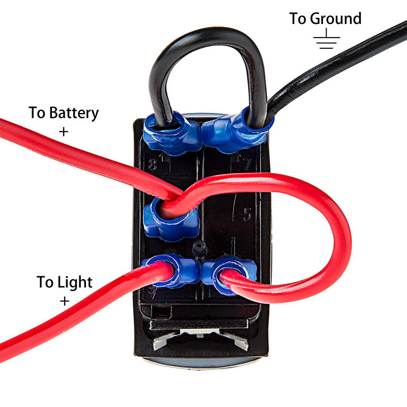
A Carling switch wiring diagram is a visual representation of how the switch's terminals connect to the power source, the load, and any other components in the circuit. It serves as a roadmap, guiding you through the wiring process and ensuring correct connections. These diagrams are essential for both novice and experienced installers. Common issues encountered when working with Carling switches include incorrect wiring configurations, which can lead to malfunctioning accessories or even short circuits. Understanding the diagram and double-checking your connections are vital to avoid these problems.
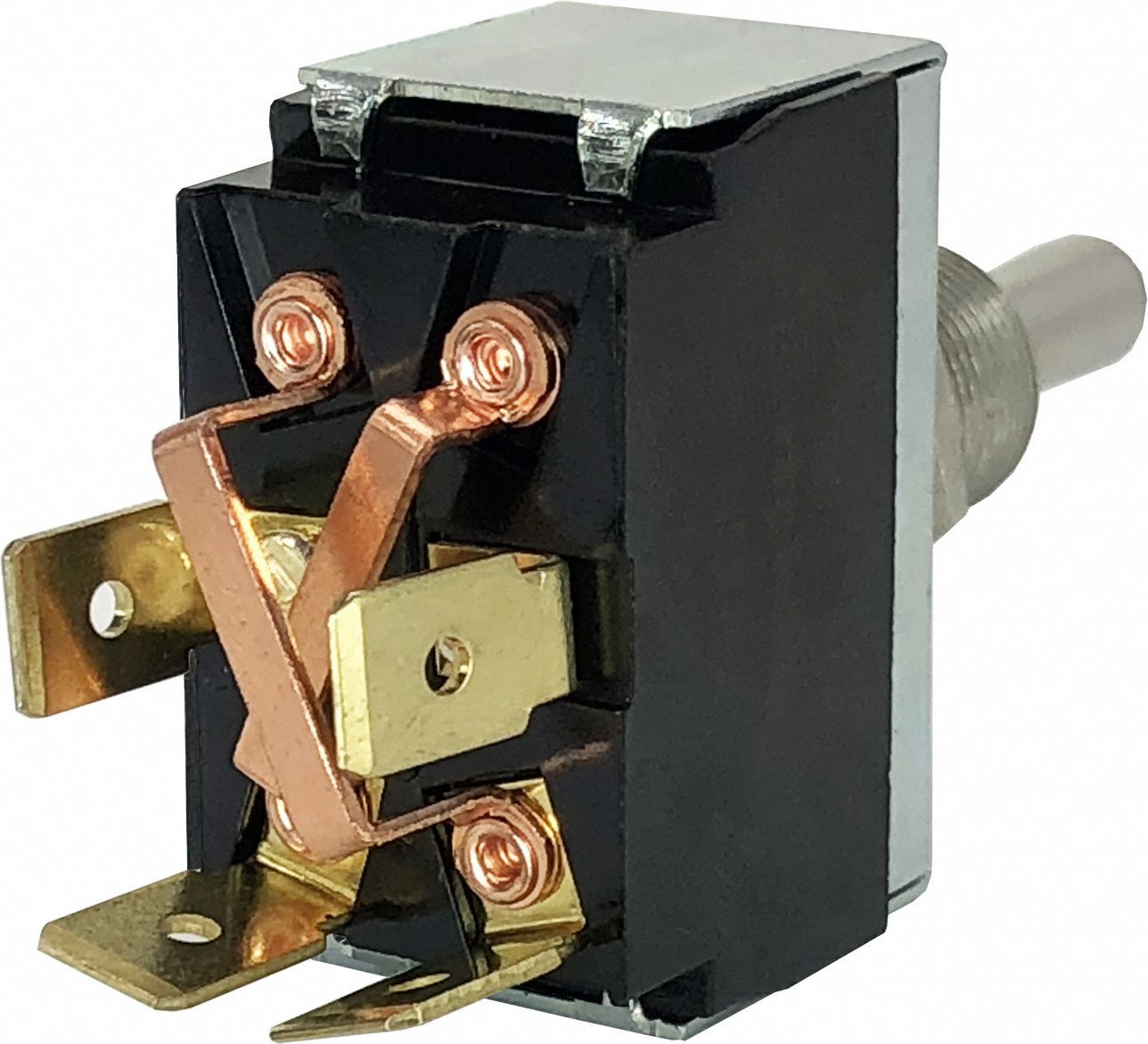
Different Carling switch configurations cater to various applications. For instance, a single-pole single-throw (SPST) switch controls one circuit, while a double-pole double-throw (DPDT) switch controls two circuits independently. Understanding these variations and their corresponding Carling switch connection diagrams is key to choosing the right switch for your needs. A simple example is a SPST switch controlling a set of fog lights; when the switch is flipped on, the circuit closes, and the lights illuminate. Conversely, flipping the switch off opens the circuit, turning off the lights.
Implementing proper techniques when dealing with a Carling switch wiring plan ensures safety and efficiency. Thoroughly inspect all wiring components for any damage or wear, and use appropriately sized wires and connectors to handle the expected current load. Always disconnect the power source before working on any electrical connections, and secure all wiring neatly to prevent interference and potential shorts.
Advantages and Disadvantages of Carling Switches
| Advantages | Disadvantages |
|---|---|
| Durable and Reliable | Can be more expensive than simpler switches |
| Versatile Configurations (SPST, DPDT, etc.) | Requires understanding of wiring diagrams |
| Weather-Resistant Options Available | May require specific mounting hardware |
Frequently Asked Questions:
1. What is a Carling switch wiring diagram? - A visual guide for wiring.
2. Why is a Carling switch wiring diagram important? - Ensures proper functionality and safety.
3. Where can I find Carling switch wiring diagrams? - Manufacturer websites and online resources.
4. What are the different types of Carling switches? - SPST, DPDT, and more.
5. How do I choose the right Carling switch? - Based on the application and required functionality.
6. What are common problems with Carling switch wiring? - Incorrect connections, loose wires.
7. How do I troubleshoot a Carling switch circuit? - Check wiring, fuses, and the switch itself.
8. Where can I get help with Carling switch wiring? - Online forums, electricians, or automotive professionals.In conclusion, mastering Carling switch wiring diagrams is essential for anyone working with automotive or marine electrical systems. Understanding the different switch types, interpreting the diagrams, and following best practices ensures the safe and reliable operation of your accessories. From simple on/off switches to complex multi-pole configurations, the knowledge gained from this guide empowers you to confidently tackle any Carling switch wiring project. So, equip yourself with the right tools and knowledge, and take control of your vehicle's electrical system like a pro! Remember, safety always comes first, so if you're unsure about any aspect of the wiring process, consult a qualified electrician.
Carling Switch Wiring Diagram 3 Pin - Trees By Bike
Rocker Switch Wiring Diagrams - Trees By Bike
Diagram How To Wire Rocker Switch Panel - Trees By Bike
5 Pin Relay Wiring Diagram - Trees By Bike
Carling Switch Wiring Styles - Trees By Bike
carling switch wiring diagram - Trees By Bike
Carling Rocker Switch Wiring Diagram - Trees By Bike
Carling On Off On Rocker Switch Wiring - Trees By Bike
Carling On Off Switch Wiring Diagram - Trees By Bike
Carling Switch Wiring Diagrams - Trees By Bike
Carling Rocker Switch Independent lamp wiring diagram - Trees By Bike
Carling Switches Wiring Diagram - Trees By Bike
Carling Switch Wiring Diagram 6 Pin - Trees By Bike
Rocker Switch Wiring Diagram 5 Pin - Trees By Bike
Carling 3 Blade Switch Wiring Diagram - Trees By Bike


