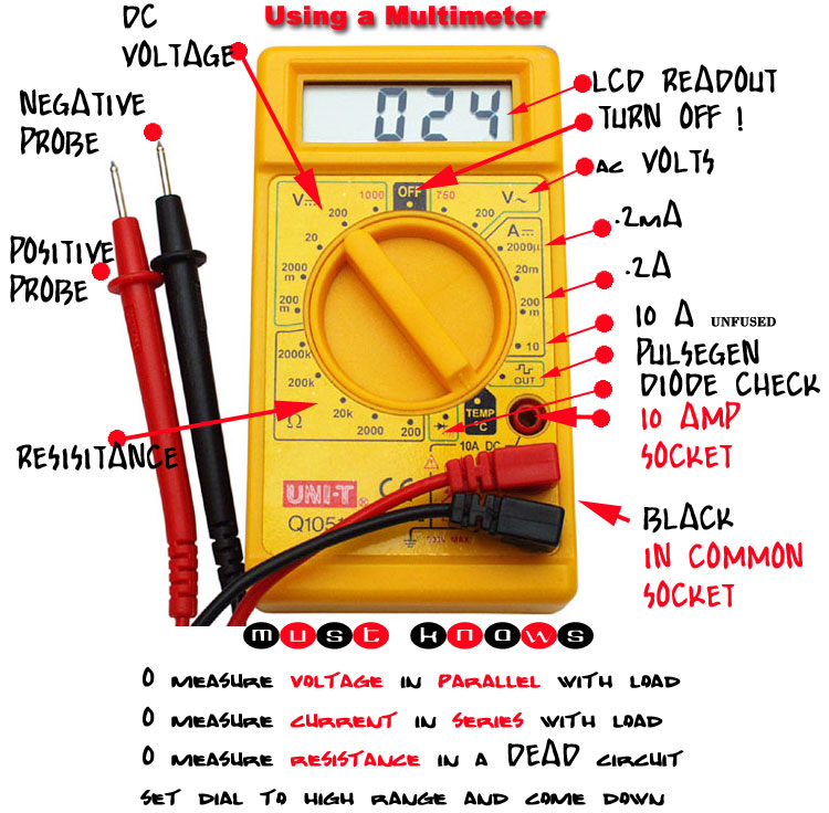
Electricity, the invisible force powering our world, relies on clear communication. Imagine trying to read a map without understanding the symbols. Similarly, electrical circuits depend on symbols to represent different components, including the crucial distinction between alternating current (AC) and direct current (DC) voltage. These symbols aren't just arbitrary marks; they are the language of electrical engineering, enabling us to understand and work with electrical systems effectively.
AC and DC voltage represent two fundamental ways electricity flows. Direct current, as its name suggests, flows consistently in one direction. Think of a battery powering a flashlight—a steady stream of electrons moving from the negative to the positive terminal. Alternating current, on the other hand, periodically reverses its direction. This back-and-forth flow is the type of electricity delivered to our homes and businesses by power grids.
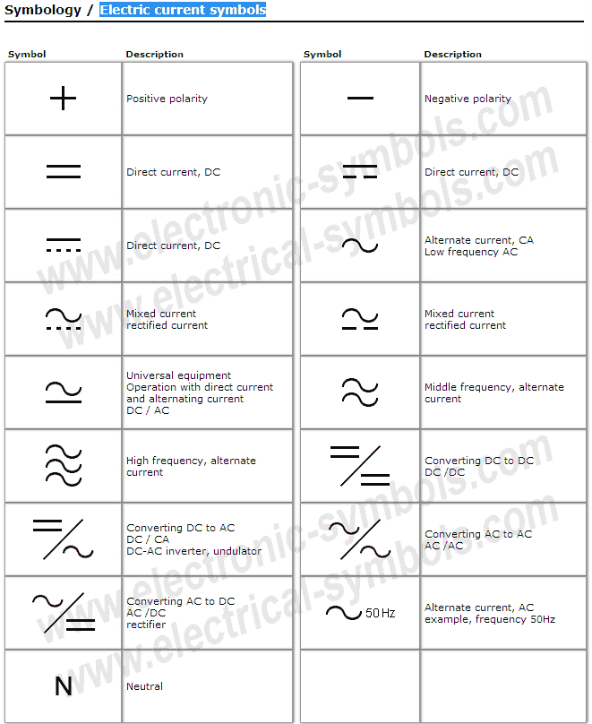
The distinct nature of these currents necessitates different symbols. The DC voltage symbol is typically a straight line with a dashed line below or sometimes a single plus and minus sign, representing its constant polarity. The AC voltage symbol, reflecting its oscillating nature, is a wavy line, sometimes referred to as a sine wave. Recognizing these symbols is fundamental for anyone working with or learning about electrical circuits.
Historically, the need for standardized symbols arose with the increasing complexity of electrical systems. Early experimenters might have used ad-hoc notations, but as electricity became a widespread technology, universal symbols were essential for clear communication and collaboration among engineers and scientists. These symbols evolved alongside the technology, becoming more refined and standardized over time. The International Electrotechnical Commission (IEC) plays a significant role in maintaining these standards today.
Understanding these symbols is not just about theory; it’s crucial for practical safety. Misinterpreting an AC symbol for a DC one, or vice-versa, can lead to dangerous situations, including equipment damage or even electric shock. Imagine connecting a DC device to an AC outlet without understanding the difference in voltage characteristics—the results could be catastrophic. Correctly identifying voltage types is paramount for safe electrical work.
The AC symbol, representing a sinusoidal wave, visually communicates the alternating nature of the current. A simple example is the symbol found on the back of many appliances, indicating they are designed for AC power. The DC symbol, often a straight line with a dashed line underneath, indicates a steady, unidirectional current, commonly seen on battery compartments or DC power adapters.
The benefits of standardized symbols are threefold: clarity, safety, and efficiency. Clarity ensures that anyone working with an electrical diagram understands the components involved. Safety is enhanced by preventing misconnections and ensuring the correct voltage type is used. Efficiency is improved because standardized symbols eliminate ambiguity and speed up the design and troubleshooting processes.
Advantages and Disadvantages of Standardized Symbols
| Advantages | Disadvantages |
|---|---|
| Clear communication and understanding | Requires learning and memorization |
| Enhanced safety in electrical work | Can be subtle differences between symbols |
| Improved efficiency in circuit design | Variations in standards across regions |
Best practices for using these symbols include adhering to established standards like those from the IEC, using clear and legible diagrams, and double-checking symbols in critical applications. Real-world examples include the markings on power supplies, wall outlets, and electrical schematics.
Challenges in using these symbols can include variations in regional standards and the increasing complexity of modern electrical systems. Solutions involve ongoing education, referencing updated standards, and utilizing software tools that ensure symbol accuracy.
Frequently Asked Questions:
What is the difference between AC and DC voltage? AC voltage periodically reverses direction, while DC voltage flows consistently in one direction.
Why are symbols important in electrical circuits? Symbols provide a clear and concise way to represent different components and voltages, ensuring clear communication and safety.
What are the standard symbols for AC and DC voltage? The AC symbol is a wavy line, while the DC symbol is a straight line with a dashed line underneath or a plus and minus sign.
Where can I find more information about electrical symbols? Resources include the IEC website, electrical engineering textbooks, and online circuit design tools.
What are the risks of misinterpreting voltage symbols? Misinterpreting voltage symbols can lead to equipment damage, electric shock, and other hazardous situations.
How can I ensure I'm using the correct symbols? Refer to established standards, use reliable resources, and double-check symbols in critical applications.
Are there different standards for electrical symbols in different regions? Yes, some variations exist, so it's essential to be aware of the applicable standards in your area.
What are some tips for learning electrical symbols? Start with the basics, practice regularly, and use visual aids to reinforce your understanding.
Tips and tricks for working with these symbols include using mnemonic devices to remember them and practicing drawing circuits with the correct notations. Online resources and software tools can also assist in learning and applying these symbols correctly.
In conclusion, understanding the symbols for AC and DC voltage is fundamental to working safely and effectively with electrical systems. These symbols are more than just simple marks; they represent a universal language that facilitates clear communication, enhances safety, and improves efficiency in the world of electricity. From designing circuits to troubleshooting appliances, these symbols play a crucial role. By embracing the importance of these symbols and continually learning about their applications, we can navigate the complex world of electricity with confidence and competence. By mastering this language of electricity, we ensure the safe and efficient operation of everything from household appliances to complex industrial systems, empowering us to harness the power of electricity effectively and safely.
Ac Power Supply Schematic Symbol - Trees By Bike
Electric Current Symbol Discount - Trees By Bike
Voltage Symbol On Multimeter - Trees By Bike
Common Electronic And Electrical Symbols - Trees By Bike
Low Voltage Wiring Symbols - Trees By Bike
How To Connect Multimeter In Series - Trees By Bike
Direct and alternating current dc and ac symbol Vector Image - Trees By Bike
symbols for ac and dc voltage - Trees By Bike
Ac Source Schematic Symbol - Trees By Bike
Inductance Symbol On Multimeter - Trees By Bike
Dc Voltage Symbols Circuit Diagram - Trees By Bike
How to Use a Multimeter to Measure Voltage Current and Resistance - Trees By Bike
Power Source Schematic Symbol - Trees By Bike
symbols for ac and dc voltage - Trees By Bike
15 Multimeter Symbols Meaning Function and Usage in 2024 - Trees By Bike


