In the world of electrical engineering and automation, clear communication is crucial. Imagine trying to decipher a complex circuit diagram without a standardized way to represent components. This is where the International Electrotechnical Commission (IEC) steps in, providing a globally recognized set of symbols, including those for limit switches. These symbols are vital for ensuring clarity and understanding in electrical schematics and documentation.
Limit switches, essential components in various automated systems, require accurate representation in circuit designs. Understanding the IEC symbol for a limit switch is fundamental for anyone working with these devices, from design engineers to technicians on the factory floor. These symbols provide a shorthand that transcends language barriers, ensuring consistent interpretation across international projects.
The IEC’s standardization efforts provide a common visual language for electrical and electronic systems. The IEC symbols for limit switches, along with symbols for other electrical components, allow engineers worldwide to collaborate effectively, reducing the risk of misinterpretation and errors. This standardization simplifies the design, installation, and maintenance of complex automated systems.
The IEC has a long history of developing and maintaining international standards for electrical and electronic technologies. The origin of standardized symbols, including those for limit switches, stems from the need for a universal language in electrical diagrams. This history emphasizes the importance of consistent representation to facilitate communication and collaboration in a rapidly evolving technical field.
One of the main issues addressed by the IEC symbols for limit switches is the ambiguity that can arise from using different or non-standardized representations. Using a globally recognized standard minimizes confusion and ensures that everyone involved in a project interprets the diagrams the same way. This clarity is critical for safety, efficiency, and successful project implementation.
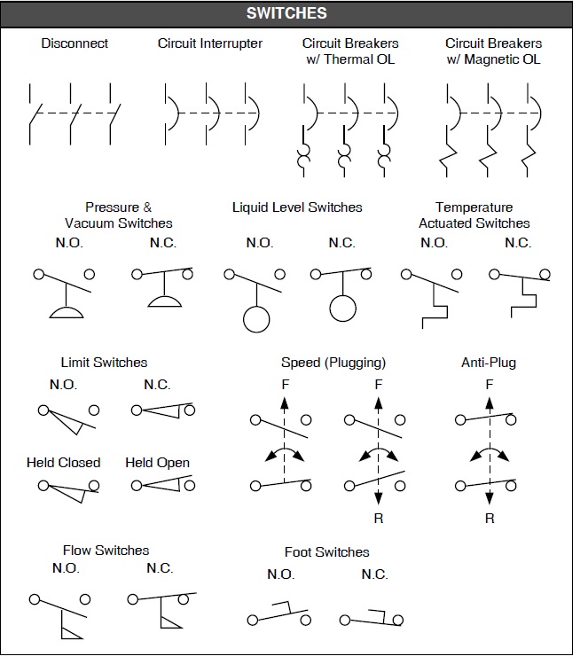
A limit switch is an electromechanical device that detects the presence or absence of an object by using a physical actuator. The IEC symbol visually represents the function of different types of limit switches, such as normally open (NO) and normally closed (NC) configurations. A normally open limit switch is represented by a symbol showing an open contact that closes when activated. A normally closed limit switch shows a closed contact that opens when activated. These symbols are incorporated into circuit diagrams to clearly indicate the position and function of limit switches within the system.
Benefits of using IEC symbols for limit switches include enhanced clarity in diagrams, reduced ambiguity in international projects, and improved communication between engineers and technicians. For example, a technician troubleshooting a machine can quickly identify a limit switch on a diagram thanks to its standardized symbol, regardless of the machine's origin or the technician's native language. This saves time and reduces the risk of errors.
One best practice is to always consult the latest IEC standards when working with limit switch symbols to ensure accuracy and compliance. When designing a control system, clearly label all limit switches in the diagram using the correct IEC symbols and ensure consistency throughout the documentation.
A real-world example of limit switch application is in an elevator system. Limit switches are used to stop the elevator at the correct floor levels, preventing overtravel and ensuring passenger safety. In a manufacturing setting, limit switches might control the movement of a robotic arm, ensuring it stops at the correct positions for picking and placing parts.
A common challenge is keeping up with updates to the IEC standards. The solution is to subscribe to IEC updates and ensure all design software and documentation reflects the latest revisions. Another challenge is ensuring all team members understand and use the correct symbols. Regular training and access to reference materials can address this issue.
Advantages and Disadvantages of Standardized Limit Switch Symbols
| Advantages | Disadvantages |
|---|---|
| Improved Clarity | Requires Learning the Standard |
| International Compatibility | Potential for Confusion with Outdated Standards |
Frequently Asked Questions:
1. What is the IEC? (International Electrotechnical Commission)
2. What is a limit switch?
3. Why are standardized symbols important?
4. Where can I find the official IEC standards?
5. How do I interpret the different limit switch symbols?
6. What are the different types of limit switches?
7. How are limit switches used in automation?
8. What are some common problems with limit switches?
Tips for using limit switches include selecting the correct type of limit switch for the application, ensuring proper installation and wiring, and regularly testing the functionality of the switches to prevent unexpected failures.
In conclusion, understanding and utilizing IEC symbols for limit switches is crucial for anyone involved in electrical engineering, automation, and control systems. These standardized symbols provide a common language that facilitates clear communication, reduces ambiguity, and enhances safety in design, installation, and maintenance. By adhering to IEC standards and best practices, engineers and technicians can ensure efficient and reliable operation of automated systems worldwide. Embracing standardized symbols is an investment in clarity, efficiency, and safety, contributing to the overall success of technical projects. The benefits of clear communication and reduced errors outweigh the effort required to learn and implement these standards, ensuring smooth operation and collaboration in complex technical projects. By continuing to learn and adapt to evolving standards, professionals can contribute to a safer and more efficient industrial landscape. Familiarizing yourself with resources like the IEC website and relevant handbooks can further solidify your understanding and contribute to professional development in this critical area.
Electrical Schematic Symbols Pressure Switch - Trees By Bike
iec symbol for limit switch - Trees By Bike
Electrical Symbols For Limit Switches Dpst - Trees By Bike
Limit Switch Schematic Symbol - Trees By Bike
Bs En 60617 Circuit Diagram Symbols - Trees By Bike
Electrical Diagrams Standards And Symbols - Trees By Bike
Flow Switches What are they Uses Types Installation - Trees By Bike
electrical diagram symbols normally open switch - Trees By Bike
Electrical Schematic Switch Symbols - Trees By Bike
Switch Symbol Circuit Diagram - Trees By Bike
Toggle Switch Symbol Iec - Trees By Bike
Us Hs Code For Pressure Sensor at Catherine Brinkmann blog - Trees By Bike
Limit Switch Schematic Symbol - Trees By Bike
One Line Diagram Symbols Standards - Trees By Bike
iec symbol for limit switch - Trees By Bike


