Imagine trying to navigate a complex city without a map. Frustrating, right? Similarly, in the world of electronics, DC electrical schematic diagrams serve as the essential roadmap for understanding and working with direct current circuits. These symbols, a universal language for electrical engineers and technicians, represent various components and their connections, allowing for efficient design, analysis, and troubleshooting. Mastering these symbols is crucial for anyone working with DC circuits.
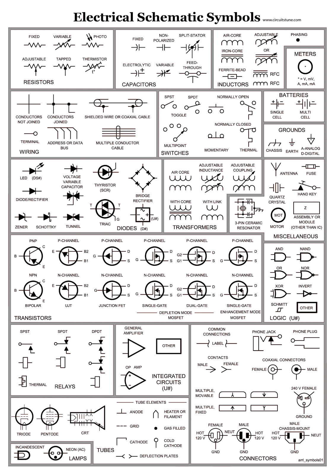
DC electrical schematic symbols are simplified graphical representations of electrical components used in direct current circuits. They provide a standardized visual language that transcends linguistic barriers, enabling effective communication and collaboration among professionals worldwide. These symbols depict everything from simple batteries and resistors to more complex devices like diodes and transistors, making it possible to represent entire circuits on a single sheet of paper.
The history of these symbols is intertwined with the development of electrical engineering itself. As the field progressed, the need for a standardized system of representation became increasingly apparent. Early schematic diagrams were often complex and varied, leading to confusion and misinterpretations. Over time, a set of standardized symbols emerged, simplifying circuit design and analysis and paving the way for the rapid advancements in electronics we see today.
The importance of DC electrical schematic symbols cannot be overstated. They are fundamental to circuit design, allowing engineers to visualize and plan the layout of components before physically building the circuit. They are also crucial for troubleshooting, allowing technicians to quickly identify faulty components or connections. Without these symbols, the process of designing, analyzing, and repairing DC circuits would be significantly more complex and time-consuming.
One of the main issues related to DC electrical schematic symbols is the potential for misinterpretation if the symbols are not understood correctly. This can lead to errors in circuit design or analysis, potentially resulting in malfunctioning circuits or even damage to components. Therefore, a solid understanding of these symbols is essential for anyone working with DC circuits.
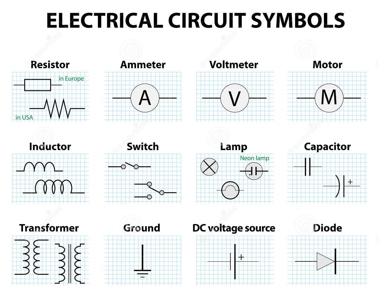
A simple example is the symbol for a battery, represented by a pair of parallel lines, one longer than the other. The longer line represents the positive terminal, while the shorter line represents the negative terminal. This simple symbol conveys essential information about the component and its polarity, allowing it to be easily integrated into a larger circuit diagram.
One benefit of using DC electrical schematic symbols is the ease of communication they provide. Engineers can share designs and ideas effectively using these symbols, even if they speak different languages. Another benefit is the simplified troubleshooting process. By following the connections and symbols in a schematic diagram, technicians can quickly isolate faulty components, saving valuable time and resources. Lastly, using standardized symbols promotes consistency and clarity in circuit design, reducing the risk of errors and misunderstandings.
To master DC electrical schematic symbols, start with a basic understanding of common components like resistors, capacitors, and diodes. Practice drawing and interpreting simple circuits, gradually increasing complexity as you gain confidence. Utilize online resources, textbooks, and software tools to reinforce your learning and explore more advanced symbols.
Advantages and Disadvantages of DC Electrical Schematic Symbols
| Advantages | Disadvantages |
|---|---|
| Clear and concise representation of circuits | Requires knowledge of symbols for interpretation |
| Facilitates communication and collaboration | Can be complex for very large circuits |
| Simplifies troubleshooting and analysis | Doesn't convey physical layout or component size |
Best practices for implementing DC electrical schematic symbols include using a consistent drawing style, clearly labeling all components and connections, and organizing the diagram in a logical and easy-to-follow manner. Always double-check your work for errors and ensure that the schematic accurately reflects the intended circuit design.
Examples of real-world applications of DC electrical schematic symbols include designing power supply circuits for electronic devices, creating wiring diagrams for automotive electrical systems, and developing control systems for industrial machinery.
A common challenge is keeping up with the evolving set of symbols as new components and technologies emerge. The solution is to stay updated with industry standards and utilize resources that provide the latest symbol information.
Frequently Asked Questions:
1. What is the symbol for a resistor? A zigzag line.
2. What does the symbol for a diode look like? A triangle with a line across one end.
3. How is a capacitor represented in a schematic? Two parallel lines.
4. What is the importance of polarity in DC circuits? Ensures correct component operation.
5. How can I learn more about DC electrical schematic symbols? Online resources, textbooks, and software.
6. What are some common mistakes to avoid when drawing schematics? Incorrect symbol usage, unclear labeling.
7. What software can I use to create DC schematics? Eagle, KiCad, Altium Designer.
8. How can I troubleshoot a circuit using a schematic? Trace the connections and check component values.
A tip for working with DC electrical schematic symbols is to use software tools that offer automated symbol placement and connection features. This can significantly speed up the drawing process and reduce the risk of errors.
In conclusion, DC electrical schematic symbols are the essential language of DC circuit design and analysis. They provide a powerful tool for communication, troubleshooting, and efficient circuit development. Mastering these symbols is crucial for anyone working in electronics, from hobbyists to seasoned professionals. By understanding the meaning and application of these symbols, you can unlock a deeper understanding of DC circuits and pave the way for successful electronic projects. Embracing these symbols isn't just about learning a technical language; it's about gaining the ability to visualize, create, and manipulate the flow of electrons, the very essence of modern technology. Take the time to study these symbols, practice their application, and stay updated with the latest standards. Your journey in the world of electronics will be greatly enriched by the understanding and mastery of DC electrical schematic symbols. They are the key to unlocking the full potential of DC circuits and bringing your electronic designs to life.
Schematic Symbol For Switch - Trees By Bike
Electrical And Electronic Circuit Symbols - Trees By Bike
Basic Circuit Schematic Symbols Voltage - Trees By Bike
Dc Electrical Schematic Symbols - Trees By Bike
Circuit Schematic Symbols Pdf - Trees By Bike
Electrical Diagram Schematic Symbols - Trees By Bike
Dc Electrical Schematic Symbols - Trees By Bike
Dc Electrical Schematic Symbols - Trees By Bike
Dc Electrical Schematic Symbols - Trees By Bike
A Letter Designation Sl On An Electrical Drawing Indicates A - Trees By Bike
Dc Electrical Schematic Symbols - Trees By Bike


