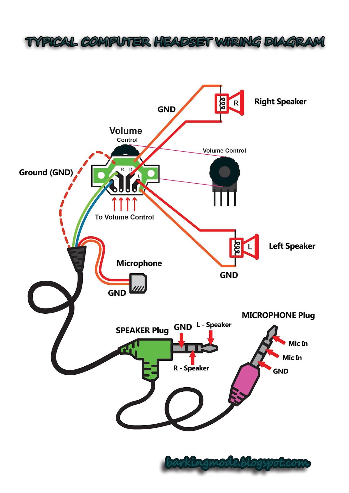
Ever wondered what lurks beneath the surface of your computer's audio input? It's a world of wires, connectors, and signals, all orchestrated by the humble yet powerful computer microphone wiring diagram. Whether you're a podcasting pro, a gamer seeking crystal-clear comms, or just curious about how your voice gets digitized, understanding these diagrams can unlock a whole new level of audio mastery. So, let's plug in and explore this often-overlooked but crucial aspect of our digital lives.
The journey of sound from your voice to your computer is a complex but fascinating one. A microphone converts sound waves into electrical signals. These signals then travel along wires, guided by the intricate pathways laid out in a computer microphone wiring diagram. These diagrams are essentially roadmaps, showing how to connect different microphone types, like dynamic mics and condenser mics, to various audio interfaces and computer ports.
The history of microphone wiring is intertwined with the development of audio technology itself. From early telephone systems to modern digital audio workstations, the principles of connecting microphones have evolved alongside our understanding of sound and electronics. Today's diagrams are more sophisticated, catering to diverse microphone types, including USB microphones, XLR microphones, and even wireless configurations. These advancements allow for greater flexibility and customization in audio setups.
Why are computer microphone wiring diagrams so important? They're the key to achieving optimal audio quality and avoiding frustrating technical issues. A correctly wired microphone ensures that your voice is captured clearly, without unwanted noise or distortion. Whether you're recording a song, participating in a video conference, or simply chatting with friends online, a proper microphone setup, guided by a wiring diagram, is essential for a smooth and enjoyable audio experience. Misinterpreting a diagram, however, can lead to silence, buzzing sounds, or even damage to your equipment.
A typical computer microphone wiring diagram might show you how to connect a microphone with an XLR connector to an audio interface, which then connects to your computer via USB. It might detail the pinout of the XLR connector, explaining which pin carries the audio signal, which pin is for grounding, and so on. For USB microphones, the diagram might be simpler, showing a direct connection to a USB port on your computer. Understanding these diagrams empowers you to troubleshoot connection problems, choose the right cables, and configure your audio settings correctly.
One benefit of understanding these diagrams is the ability to troubleshoot audio problems. If your microphone isn't working, you can consult the diagram to check if everything is connected correctly. Another benefit is the flexibility it provides in setting up your audio system. You can experiment with different microphone types and connections to find the best setup for your needs. Finally, understanding these diagrams can save you money by helping you avoid costly mistakes, like buying incompatible cables or damaging your equipment.
A simple action plan for using a microphone wiring diagram is to first identify your microphone type and the available input ports on your computer or audio interface. Then, locate the appropriate diagram for your setup, either online or in the microphone's manual. Carefully follow the diagram, ensuring each connection is secure. Finally, test your microphone to verify that it's working correctly.
Advantages and Disadvantages of Different Microphone Wiring Schemes
| Scheme | Advantages | Disadvantages |
|---|---|---|
| XLR to Audio Interface | High quality, professional-grade audio | Requires additional equipment (audio interface) |
| USB Microphone | Simple plug-and-play setup | Limited flexibility and control |
Best Practices:
1. Always double-check your connections before powering on your equipment.
2. Use high-quality cables to minimize signal loss and interference.
3. Consult the microphone and audio interface manuals for specific instructions.
4. Test your microphone setup before important recordings or events.
5. Keep your cables organized to avoid tangles and damage.
Frequently Asked Questions:
1. What is a computer microphone wiring diagram? (A visual guide to connecting a microphone to a computer.)
2. Why is it important? (Ensures proper audio signal flow.)
3. Where can I find one? (Online, microphone manuals, audio interface manuals.)
4. What are the different types of microphone connectors? (XLR, USB, TRS, etc.)
5. How do I troubleshoot microphone connection issues? (Check cables, connections, and audio settings.)
6. What are the benefits of using an audio interface? (Improved audio quality, more control.)
7. Can I connect multiple microphones to my computer? (Yes, with the right equipment.)
8. What are some common microphone wiring mistakes? (Incorrect pin connections, using wrong cable types.)
Tips and Tricks: Secure cable connections, use cable ties for organization, test different microphone placement for optimal sound.
In conclusion, the seemingly simple computer microphone wiring diagram is a vital link in the chain of digital audio. Understanding its nuances empowers us to capture sound with clarity and precision. From the earliest audio experiments to today's sophisticated recording setups, the principles of microphone wiring have shaped how we communicate and create. By appreciating the importance of these diagrams, embracing best practices, and continually learning about new technologies, we can unlock the full potential of our audio tools and bring our digital voices to life. Whether you're a seasoned audio engineer or just starting your journey, take the time to explore the fascinating world of computer microphone wiring diagrams. It's a journey well worth taking, and one that will undoubtedly enhance your audio experience. Take the time to study the diagrams relevant to your setup, and remember that practice makes perfect. The clearer your audio, the more effectively you can communicate, create, and connect with the world around you.
Pc Microphone Connection Diagram - Trees By Bike
DIAGRAM 6 Pin Wiring Diagram Headphone With Mic - Trees By Bike
Pc Microphone Connection Diagram - Trees By Bike
Headphones Color Code at Grace Greene blog - Trees By Bike
Helicopter Headset Wiring Diagram - Trees By Bike
How To Connect Mic Preamp To Interface - Trees By Bike
Microphone Plug Wiring Diagram - Trees By Bike


